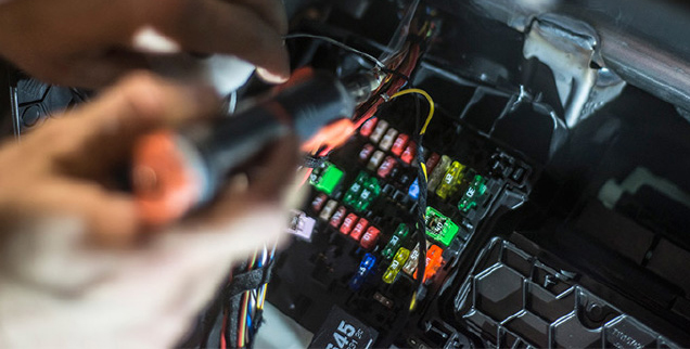
The location of the vehicle’s fuse box varies from vehicle make and model. Locations may include underneath the driver’s side dashboard, behind the glove box and underneath the central console. Where in doubt, always refer to your vehicle owner’s manual to determine the location of the fuse box in your vehicle.
*NOTE: The images in this installation were taken for a vehicle where the fuse box is located under the driver’s side dashboard (Fig. 1, 2) and should be used as a guide only for a DIY installation. To ensure proper installation Dashmate recommends DSH-HWK be installed by a professional technician.

There are 2 main stages in the hardwire kit installationThere are 2 main stages in the hardwire kit installation
• Connecting output cable to your dashcam
• Connecting input cables to your fuse box and grounding
NOTE: Determine the location of your vehicle’s fuse box before commencing the installation of the hardwire kit. Where in doubt, refer to the vehicle owner’s manual.
CONNECTING HARDWIRE KIT TO YOUR DASHCAM
IMPORTANT: Refer to your dashcam owner’s manual for initial installation of your dashcam in your vehicle.
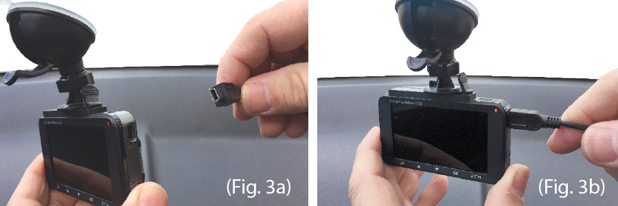
ATTACHING THE USB CONNECTOR TO THE DASHCAM
1. Two dashcam connector cables are included with DSH-HWK – one with a Mini USB plug and one with a Micro USB plug. Determine the connection interface type on your dashcam and then select the appropriate USB connector cable. (Fig 3a)
2. Insert the USB connector cable to your dashcam (Fig 3b)
ROUTING THE OUTPUT CABLE FROM THE DASHCAM TO THE FUSE BOX
*NOTE: You may need to consult your vehicle manufacturer for instructions on how to remove vehicle fittings (example A pillar cover) for routing the hardwire kit cables inside your vehicle and for where airbags are located so that these are not obstructed in case of deployment by routed cables.
INSTALLING THE OUTPUT CABLES IN VEHICLE
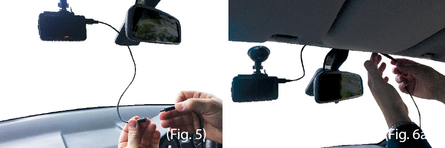
1. Once the USB connector cable is attached to your dashcam, it then needs to be connected to the hardwire kit’s output cable. (Fig 5)
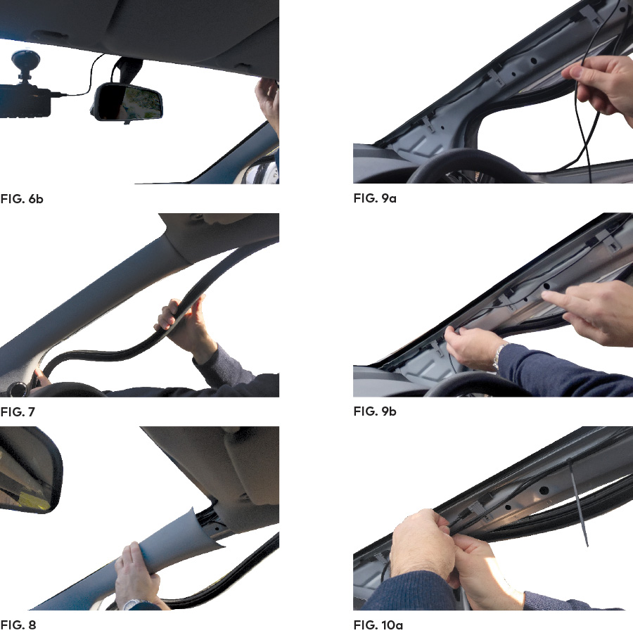
2. The hardwire kit output cable will then need to be recessed into the roof lining where it meets the edge of the windscreen to conceal the cable (Fig 6a, 6b)
3. At the farthest end of the roof lining the output cable needs to then be routed along the A pillar that is closest to the fuse box of the vehicle. You will need to remove the door seal (Fig 7) and A pillar cover (Fig 8) to route the cable (Fig 9a, 9b). Route the cable all the way down to the end of the A pillar where it meets the dashboard.
4. Use the provided cable ties to attach the output cable to any existing cable(s) that may be housed in the A pillar (Fig 10a).
*NOTE: The A pillar used to route the cable is not always the driver’s side one as shown. Refer to the vehicle owner’s manual to determine location of fuse box in your vehicle. The output cable needs to be routed in the A-pillar closest to the fuse box.
HOUSING THE OUTPUT CABLE
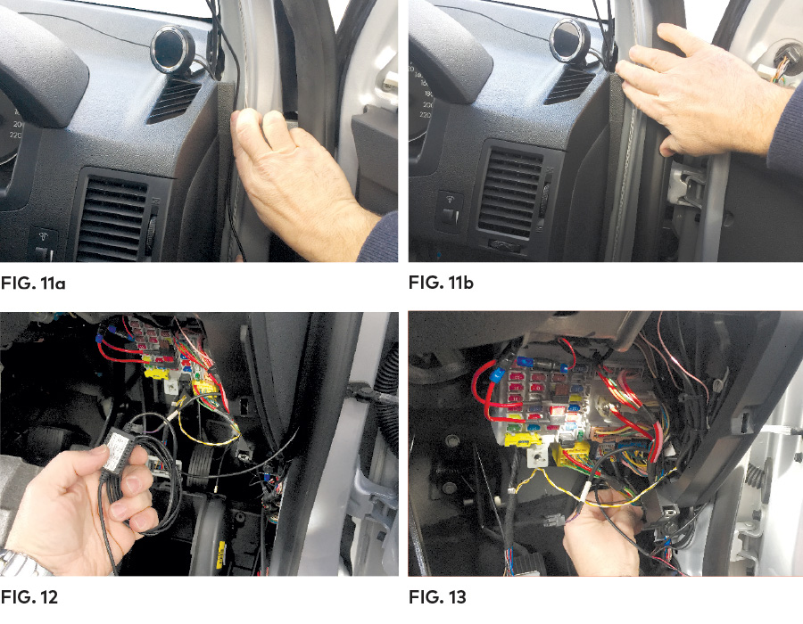
1. Where the output cable from the A pillar meets the side of the dashboard, the output cable will then need to be routed towards the direction of the fuse box by concealing the cable along the side of the vehicle dash (Fig 11a, 11b).
2. Any excess output cable length can be wrapped and held together with a cable tie when it reaches the fuse box (Fig 12)
3. Tuck away any excess output cable behind the fuse box (Fig 13)
4. If required, peel off the control box label to attach the control box to the vehicle (near the fuse box) with the adhesive tape.
CONNECTING TO THE FUSE BOX
NOTE: Refer to your vehicle’s fuse layout panel to determine the permanent power fuse for constant power feed. The fuse cable needs to be connected to the 12V/24V battery feed.
1. Determine the fuse tap cable required for connection to your fuse box. Where in doubt refer to the vehicle owner’s manual.
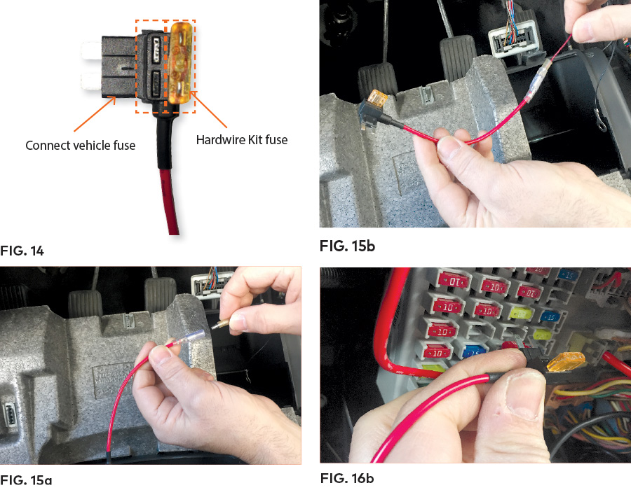
2. Place the vehicle fuse in the fuse tap cable. Note the correct position location for both the vehicle fuse and the hardwire kit fuse in the fuse tap cable (Fig 14).
3. Locate the input cable and connect the fuse tap cable to the red input connector (Fig 15a, 15b). Ensure connection is secure.
4. Insert the fuse tap into the fuse box (Fig 16b).
5. Tuck away any excess red input cable behind the fuse box.
*NOTE: To determine constant and ACC power feeds fuse use a voltage meter.
CONNECTING TO GROUND
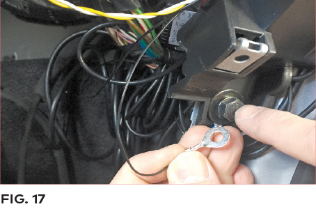
1. Locate earth terminal/bolt or any vehicle bolt accessible that is mounted to the chassis of the vehicle or any metal part of the vehicle – located near the vehicle fuse box (Fig.17).
2. Feed black input wire eyelet into bolt and screw bolt back on existing location.
3. Tuck away any excess input cable behind the fuse box.
*NOTE: The black earth cable needs to be connected to the vehicle chassis otherwise it will not earth out.